

I thought I would knock some dust off my drafting skills after a small chat with @captain_aggravated@sh.itjust.works
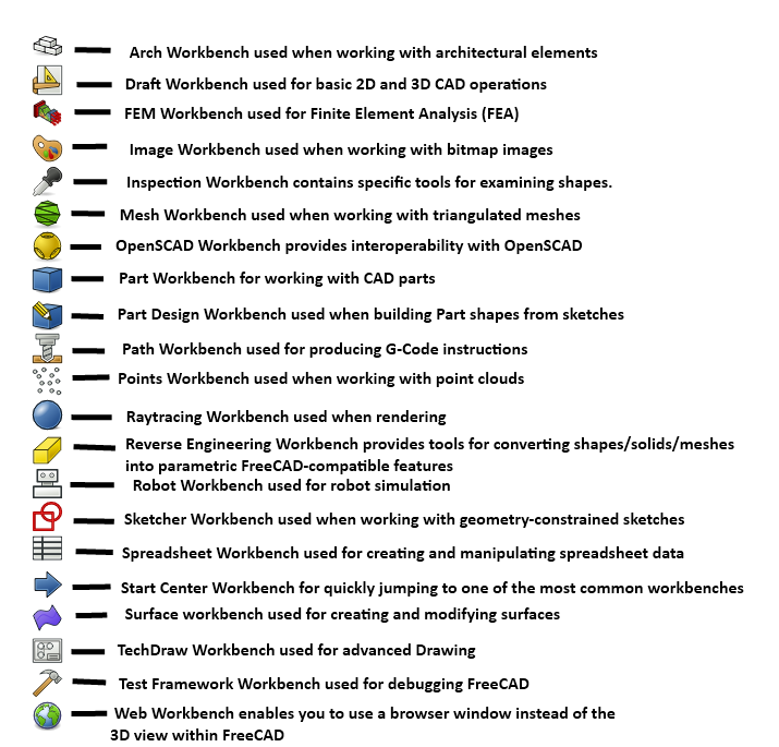
Seeing this image on the tutorial made me realize, FreeCAD seems to be a Technical Geometry Super-Suite. It makes sense that CAD would grow to include all of these things. But I thought sharing the initial perspective of some one who hasn’t looked at this stuff in about 18 years might be interesting.
Granted I’m not actually familiar with most of this stuff, and none of it from the POV of FreeCAD. If this can deliver 10% of what I’m looking at, I’m in for a treat.
Curious to hear what it’s like making parts with a spreadsheet. Is it like coding?
I use openscad a lot, and just tried using spreadsheets – adding parameters to each property in a part still seems really clunky, compared to editing a scad file in Emacs, which I vastly prefer, especially now that there’s AI code autocomplete.
It is very slightly like coding, it helps to understand Python’s syntax because as you get into things like the macro system and referencing cells in a spreadsheet, you’re skimming the upper atmosphere of FreeCAD’s Python API.
Just about every text box in FreeCAD where you can enter a dimension as a literal number, like using the dimension tools in the sketcher for example, you’ll notice a little f(x) button. That means you can also put in an expression as well. It can be as simple as “I don’t want to divide 6.675mm by four in my head right now” so you type in =6.675mm/2, or you can reference other objects. So you can do something like =overallThickness/2 to drill a hole halfway through something.
The spreadsheet workbench gives you somewhere centrally to put in values, do those calculations, things like that. You can then refer to them when sketching and part designing; say you name your spreadsheet “Sheet”, you can refer to a cell like =Sheet.B2. Or, you can give individual cells an alias, so you can have Sheet.overallThickness.
It works a bit like the Parameters feature in Fusion360, but more functional. It is a bit clunky out of the box, but there are a few macros available in the Addon Manager that let you highlight a column of cells, and it will apply the contents of each cell as the alias of the cell to it’s right, there’s another that allows you to click a line in the Sketch workbench, click a cell in the spreadsheet, and with one button click assign that cell’s value as the dimension, and it’s semi-smart as to what kind of dimension you need.
I find that doing it this way versus entering literal values into sketches puts all the dimensions in one place where I can read them all, and I don’t mix up values that happen to be the same but for different reasons, which can screw you over if you have to make an alteration later. “Ugh, I have to go through like five sketches and change all those 4.5mm dimensions to 5mm. Wait why is that wrong? Oh not THAT 4.5mm…” I also try to do as much of my math in the spreadsheet as possible instead of having them in sketches, partially because again they’re all in one place and easy to check, alter and fix, but also because that spreadsheet becomes a useful part of the set of drawings once I go out to the shop to build the thing I’ve designed. There are projects where I only printed the spreadsheet for reference in the shop. Note I forgot to list the Techdraw workbench, which is used to create dimensional drawings from your models, because sometimes I just don’t.
I use the spreadsheet to hold dimensions/variable and formulas, makes it easier to modify designs. If I want to change a length, hole size height etc just change the spreadsheet values don’t have to mess around with the sketches or 3d part designs directly.
One slightly frustrating thing i found is sometimes it fails to recompute the design or processes it incorrectly when values are changed by large amounts, that’s probably more to do with how I design things though
I’ve seen it do things like that for two reasons:
If your change causes the number or arrangement of faces to change, this currently breaks things. This is what people in this thread talking about the topological naming issue are about; it keeps track of which faces are which by giving them names when they are created, and then when another feature is added to that face, it’s linked by name. If you go back, edit an earlier step which creates more or fewer faces, it recomputes the model and might name them differently, so features suddenly move.
Sometimes I’ve had the sketcher just decide to turn a sketch inside out, because sometimes things like tangent constraints have two stable ways to be “fully constrained” or the existing constraints make different shapes with different dimension numbers.
I have seen both issues, when the sketcher starts to play up sometime I add more constraints to try to “anchor” a tangent in a certain direction but it can make the sketch messy The most reliable way I’ve found to stop it is small incremental changes e.g. say I want the length of a part to change my 40mm I’ll change the size in 5mm increments allowing FC to recompute the model between each step. It’s fiddly and frustrating but I can live with it, once you get to understand it’s quirks Freecad can be very useful