
![[PCB Review Request] A choc-spaced 56 key wireless build](https://lemmy.world/pictrs/image/da52a9d0-adef-4700-98df-0d3bda9f5735.jpeg)
Hey everyone!
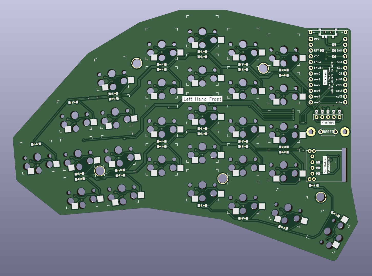
I jumped into the ergomech rabbit hole sometime last year and after using a sofle as my daily driver since then, I now decided it’s time to build my own “thing”. After going through endless revisions to figure out what I actually want, and trying to learn how to trace PCBs, this is what I have come up with: A choc-spaced 56 keys wireless build with a scrollwheel and some staggering.
It’s a reversible PCB. To make this work with single pin hole for both sides, I used jumpers for pins that can not be set in software (VCC, GND, RST). For rows/columns, I plan to do a different mapping in software to not have a jumper for every single pin.
All files including the kicad_pcb and ergogen config are available and open source at github: https://github.com/dnlbauer/splitkeyboard .
However, this is the first thing I ever designed. Therefore, I was hoping if you guys could have a look at the PCB before I get it etched and point out if there are any obvious errors?
Of course, I am also happy about any feedback in general. :)
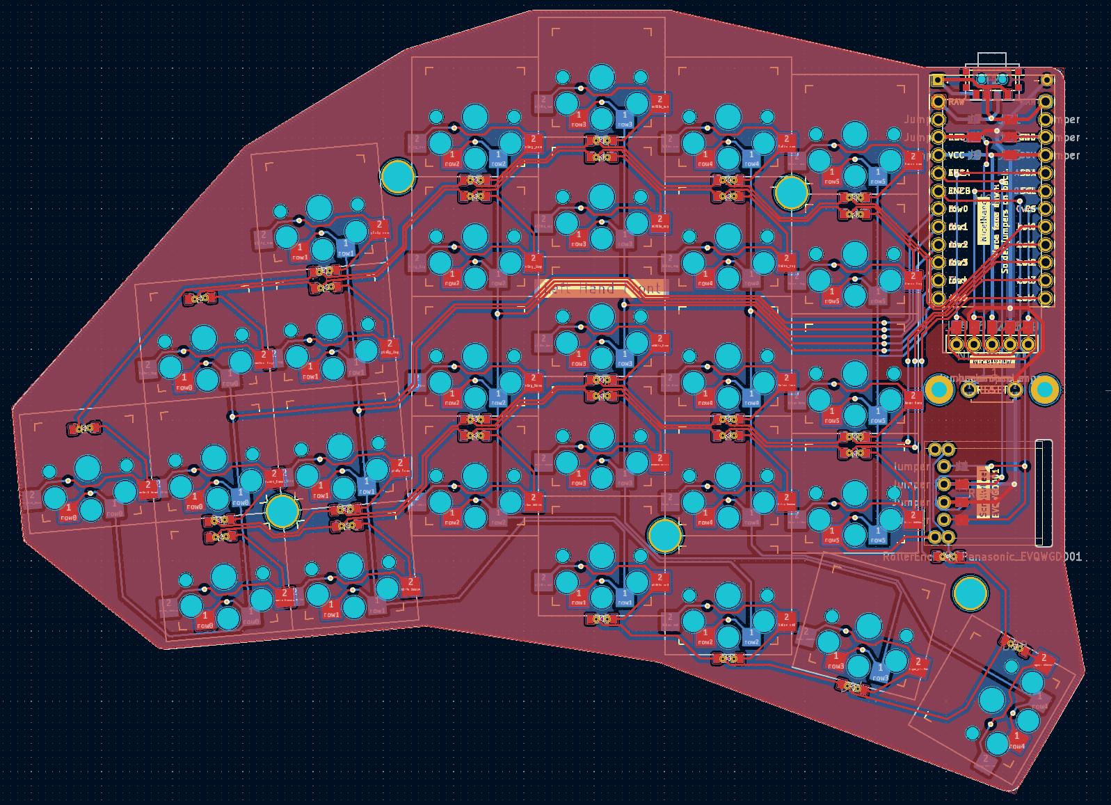
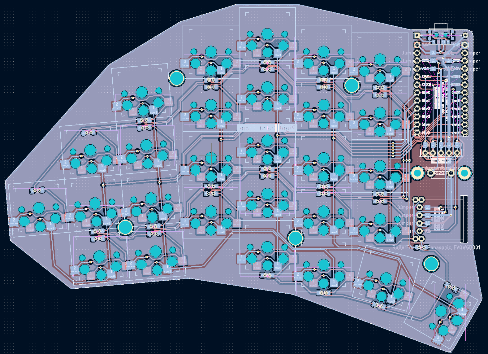
thanks for the imput. Do you mean I should just place some random vias to connect both sides of the ground plane? To be honest, I dont understand exactly what this ground plane is used for since none of the traces actually connect to it. Is it merely for shielding against signal noise?
I’m no electrical engineer. But I was informed that having the return to ground close to all data connections is a good thing from a EMI and signaling perspective. I often put ground vias near all my rows and column pads.